
997 C4 Amplifier Rack Installation for Porsche 911

Whats Involved in Installing a C4 997 Amplifier Kit.
- Mount the Amplifier
- Mount the Fuse Holder
- Route the cables
- Make Connections at Radio
Mounting The rack
Center the amp rack on the trunk floor. The rack simply sticks down and does not require any modification to the vehicle. All cabling can be routed under the factory trunk carpet. Once the amplifier has been wired and adjusted it can be concealed with the supplied carpeted cover. The cover simply presses in place.


Above left, you can see how the amplifier is situated in the vehicle. Above right, you can see how the included carpeted amplifier cover conceals the amplifier and all wiring. The cover is carpeted in the same type of material as the factory trunk liner. The whole Assembly is only 4" tall. Once in place, it's nearly undetectable.
Route the Cables
Note: '05 - '08 and '09 - '13 vehicles
Many of the pictures and descriptions in this article show an '05 - '08 vehicle. '09 - '13 vehicles are the same except the factory amplifier is located under the passenger side seat. The pre-wired harnesses that come with your kit will be tailored and labeled for your specific vehicle.
Your new amplifier will arrive pre-mounted to the amp rack and pre-wired with power and speaker output extensions.
Step 1. Disassemble
Remove plastic panels in the trunk.
Remove the battery cover.
Remove the plastic panels to the left and right of the battery.
Remove the long black plastic strips along each side of the trunk opening.
Remove the trunk courtesy light and unplug.
Remove the small torx fasteners from the large plastic center panel and remove panel.
Grounding the Amplifier
On C4 vehicles we recommend grounding the amplifier directly in the trunk area. Ideally the ground lead should be as short as possible. Crimp on the the supplied ring terminal and use the supplied self tapping screw and ground to the hallow double walled steel structure on the lower side of the trunk. The double walled sections of the trunk floor are ideal grounding locations because the tip of your grounding screw will not be exposed to the elements. Be sure that you are not screwing into any critical components on the other side! check twice. Make sure to sand away all paint at the point of contact to ground so that you have a clean metal to metal connection.
Radio Ground Reference

Each amplifier kit comes with a Black and Blue pair of cables already connected to your new amplifier. The black wire is a radio ground reference. It should be used as a grounding point for your radio instead of the factory ground that is located in the factory radio wire harness. Using this grounding point will greatly reduce the chances of any unwanted radiated electrical noise from entering the audio system. The Blue wire is the amplifiers remote-turn-on circuit. Connect this wire to the radio's Blue with White stripe wire.
Routing the Signal Cables & Power Cable
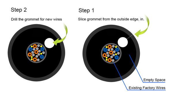
RCA signal cables, radio reference ground, remote-turn-on, power, and speaker cables (depending on which amplifier and configuration you are using), will need to be routed into the passenger compartment of the vehicle. There are two large factory rubber grommets on the wall separating the trunk from the battery compartment. One on the far left side and one on the far right side. These grommets are thick and heavily populated. There is plenty of room if you notch the grommet. Pull the grommet out from the steel hole. You will then be able to slice the grommet from the outside edge inward. Then notch a space for your new wires.
Alternatively you can use a step drill bit (Unibit) or a paddle bit to bore a hole through this grommet. Take care not to cut into existing factory wiring!
Additionally you can choose to run your RCA cables separately from the rest of the cabling. Run your RCAs through the left side grommet (drivers side), and runn the rest of your cables through the right side grommet.
To make it easier to push the grommet back into place, wet the grommet with glass cleaner first.
Moving the Battery
Once the cables are in the battery compartment you will want to slide the battery to the passenger side of the vehicle to gain access to the grommet that leads into the passenger compartment. Remove the 13 mm battery hold down bolt on the passenger side of the battery. Remove the negative battery terminal and slide the battery towards the passenger side of the vehicle. This will give you easy access to the large rubber grommet between the battery compartment and the passenger compartment. This grommet is located behind the drivers side of the battery. Inside of the vehicle this grommet is located just above the gas pedal. Signal (RCA), Remote (Black & Blue pair), and in some vehicles speaker wires will need to pass from the new amplifier location - through the first grommet - behind the battery - and through this grommet into the passenger compartment.
Routing Cables inside the Passenger Compartment
Once your cables are routed into the passenger compartment, you will want to be aware of the vehicles main charge cable. This is a large gauge cable that runs the length of the vehicle. This cable connects the battery to the engine in the rear and is black in color. This cable emits a lot of electrical noise. You do not want your cables to run parallel to this cable. Never zip tie your cables to this cable. You must run your cables near and past this cable. Make sure that you cross it at a 90 degree angle. this will dramatically reduce any electrical noise transfer. Below is an image of the factory charge cable.

When routing cables be aware of the gas and brake pedal operation. Keep clear of them.
Once your cables are in the vehicle and the grommet is put back in place, reconnect the battery's negative terminal, and refasten the battery hold down.
Connect the Speakers
Identify Speaker Connections at the Amplifier
 Your new amplifier will arrive with speaker output extensions already connected to it. These extensions are made with 4 conductor wire bundled in a white jacket. Each 4 conductor lead will have the following wire colors in it:
- Red = Right Positive
- Black = Right Negative
- White = Left Positive
- Green = Left Negative
Two of the 4 conductor cable will be marked with blue rings near the end of the wire loom. These rings are there to help identify which channels on the amplifier the cables are plugged into. They are as follows:
- No Ring = Channels 1 & 2
- 1 Ring = Channels 3 &4
- 2 Rings = Channel 5
About the 5th Channel Output Cable
On the 5th channel cable the two pair of speaker wire have been connected in series. This is done by connecting one positive (Red) and one negative (Green) together at the amplifier end of that cable. The reason that we do this is; when the two pair of speaker wires are connected to the vehicles door woofers, the two woofers are both connected to the amplifiers single 5th channel output in a 4 ohm configuration. Simply make the connections to the two door speakers as you normally would with a two channel output. The amplifier sees both door woofers as a single speaker. This is functionally the same way that the factory amplifier is configured.
If using the 5th channel with a single aftermarket subwoofer (see 5 Channel Configuration #2 below), remove this cable from the amplifiers output terminal and replace with a standard two conductor speaker wire.
During the installation process you will be disconnecting the factory amplifier speaker connections and reconnecting them to the new amplifier. Your new amplifier will have a speaker output harness already connected to it. The speaker connections on your new amplifier are pre-labeled.
Identify the speaker wire pairs in the factory amplifier wire harness. Speaker pairs will be twisted.
Caution! Before cutting any wires, identify the factory amplifier power cables. These will be the larges gauge wires in the harness and are located on one far end of the plug. They are typically Red (or Red/Blue) and Brown. Test these with a volt meter. You will not be using these circuits. Label them and make sure that you do not mistake them for speaker wires.
Next Identify the speaker locations associated with each pair by cutting them away from the factory plug and touching a 9 volt battery to them. This will cause the corresponding speaker to "pop". Do not hold the battery to the speaker wires for any extended length of time. This will cause damage to the speaker. A second person is handy to have around so that they can listen for speaker locations as you test them. Typical speaker wire colors are listed below. If the colors listed below match the colors your vehicle has you can opt to skip the speaker testing.
Speaker wire color chart for 911s 2005 through 2008
Models of this year range with factory amplifiers have the amplifier located up front in the trunk.

Speaker wire color chart for 911s 2009 through 2013
Models of this year range with factory amplifiers have the amplifier located under the front passengers seat.

Once you have Identified the speaker circuits, make your connections to the supplied speaker output harnesses. The supplied harnesses will be labeled. These are wire to wire connections. We advise soldering. Butt connectors work as well.
The factory amplifier harness can be rerouted from its original location so that it is closer to the new amplifier. To do this, pull back the carpet trunk liner and cut the plastic tie-downs to release the harness form the body of the car.
Make Connections at Radio
Connect the Blue and Black wire harness to the radio. Blue is amplifier remote turn-on and is connected to the Blue with white stripe wire on the aftermarket radio. If you purchased a radio with your amplifier, these connections will have a matching plug. Simply plug it in.
Connect the rear speaker pass through. Only for amplifier configurations where the rear speakers are being driven from the radio and not the new amplifier. In the event that the rear speakers need to be driven by the radios internal amplifier, we include a speaker wire run that connects to the radio harness and runs into the trunk where it connects to the factory amplifier harness with the other speaker connections. If you purchased a radio with your kit, the radio will already have a mating connector on it for this cable. Simply plug it in.
Connect the RCA signal cables to front, rear, and subwoofer. If your kit came with "Connection brand" cables the colors will be as follows:
Front = Red (right) & Black (Left)
Rear = Yellow (Right) & Green (Left)
Subwoofer = Orange (Right) & Violet (Left)
If you have a Bose Sound system and are retaining your factory Bose subwoofer, your kit will come with a special signal and remote turn-on cable. Connect this cable with the supplied "Y" adapters so that the radio subwoofer RCA outputs are shared with the amplifier in the trunk and your Bose subwoofer.
Retaining Bose Subwoofer (Bose equipped vehicles only)
The Bose subwoofer has it's own amplifier built into the woofer enclosure that is separate from the amplifier in the trunk in '05 - '08 vehicles. '09 - '13 vehicles have the main amplifier located under the passenger seat. The factory Bose subwoofer amplifier in both vehicles (the one inside the sub enclosure) can be fed subwoofer audio signal and 12 volt remote-turn-on from an aftermarket radio to retain it's function. For these vehicles we include a special audio cable that has a pair of RCAs on one end and bare wire on the other end as well as a 12 volt remote-turn-on lead. The factory subwoofer gets its audio signal from the main factory amplifier. The best place to tag this signal is at the factory amplifier plug. Unplug the factory amplifier as it will no longer be used. Make all of your speaker connections for the vehicle at this point by cutting away each circuit as you identify them and connecting them to the speaker outputs of your new amplifier. Your new amplifier will have speaker leads already connected to it that are labeled for connection.
 For Bose equipped vehicles we include a special RCA that has a blue wire loomed with it and bare wire on the other end.
Connect the end with two RCAs to the subwoofer output at the radio. "Y" adapters are included in your kit so that you can connect both the factory subwoofer as well as the door woofers to the single pair of subwoofer RCA outputs at the radio. If you have purchased one of our aftermarket subwoofers, we suggest not connecting or using the factory Bose subwoofer.
Identify the factory subwoofer signal wires at the factory amplifier plug. They are Orange for Signal + and Orange/Brown for signal -. They will be twisted together in the harness. Once you have identified these lines, cut them away from the plug and solder them to the Red and brown signal cables on the subwoofer signal cable.
Lastly Identify the subwoofer amplifier remote-turn-on wire. This will be White/Yellow. Cut this wire away from the factory amplifier plug and solder the supplied blue wire onto it. Connect the other end of this blue wire to the REM terminal on your new amplifier. This way the factory Bose subwoofer amplifier will get a 12V turn-on signal when your new amplifier does.

Orange to Red
Orange/Brown to Brown
White/Yellow to Blue
Below is a picture of a factory amplifier plug removed from the vehicle (may be different than your own). You can clearly see both signal wires and the remote-turn-on. You will want to connect to the side that goes to the Bose subwoofer and not to the plug side shown.
Orange = Subwoofer + Signal
Orange/Brown = Subwoofer - Signal
White/Yellow = Subwoofer Amplifier Remote-Turn-On

Vehicle Grommets
The grommets on C4 vehicles are heavily populated and somewhat limited on space. The Orange fiber optic lines in the drivers side grommet that seperates the battery compartment from the trunk can be removed since they will not be utilized with your new amplifier. Removing these lines will give you more room in the grommet. The grommet can be pulled out and notched with a razor blade to make even more room for the new cables.
Amplifier speaker output configuration options
C4 amplifier kits are available in 4 channel or 5 channel configurations. Below is a description of those configurations.
4 Channel

Dash tweeters and door mid-range speakers are driven by channels 1 & 2.
Door woofers are driven by channels 3 &4.
5 Channel Configuration #1

Dash tweeters and door mid-range speakers are driven by channels 1 & 2.
Rear speakers are driven by channels 3 & 4.
Door woofers are driven by channel 5 (mono).
5 Channel Configuration #2

Dash tweeters and door mid-range speakers are driven by channels 1 & 2.
Door woofers are driven by channels (3 &4 Stereo).
Aftermarket Subwoofer is driven by channel 5.
Rear speakers are driven by radio's internal amplifier.
5 channel configuration #2 is only used when an aftermarket subwoofer is being used in the system. Factory Bose subwoofers are driven by the factory Bose amplifier built into the subwoofer enclosure.