
911 (996 gen) & 986 Boxster Double DIN Radio Conversion & Installation
![]()
This article covers how to install an aftermarket radio into your 996 or 986 Porsche with emphasis on converting a factory single DIN radio location to a double DIN.
All 911 and Boxsters of the 996/986 generation that have a single DIN radio can be converted to an aftermarket double DIN radio. This modification is simple but requires one of our double DIN kits.

Removing The Factory Becker Radio
You’ll need the Becker radio removal tools, these are flat metal “keys” that fit into slots on either side of the radio’s face, near the bottom of the unit. The keys are reversible, and are labeled “top L”, and “top R”, so you can use either key on either side, just make sure that you get the corresponding key’s side “up”. Insert them so that the curved portion is towards the middle of the radio when inserting each key. The keys will each slide into these slots and “click” into place. Then simply use the keys to pull the unit out. Some times it takes a bit of a hard "tug" to get movement of the radio-just make sure each key has clicked into place first.
Becker Radio Removal Keys Come with All of Our Kits
 So there's no reason to track some down on your own.
Unplug Everything
The factory radio doesn’t have a mounting sleeve, so once it’s removed, that’s all there is to it. It unplugs at the back. There are a number of plugs and an antenna connection.
Remove Trim Panels, CD Tray & HVAC Controls
Use a nylon soft pry/panel tool or something similar to remove the "batwing" shaped panel at the very bottom of the console.
Remove the trim from around the lowest position in the console.
Remove the CD tray from the second lowest position by prying it out with the soft pry tool.
Remove the HVAC trim with the soft pry tool.
Remove the HVAC controls by unscrewing the fasteners located on each side.
Note from Rod:
Very important (97-02):
Peer into the radio opening, and you’ll see usually a single wire connected to a male terminal and metal tab on the left side of this opening. This is part of the anti-theft system, and if you merely install a new radio and the chassis of the radio rests against this “tab”, the factory alarm will not fully arm, it’ll think that the radio is/has been stolen. Before installing your new radio (unless it’s another factory Becker piece with an insulated section that rests against this tab) unplug the wire from that terminal and tape it off to ensure that it doesn’t make contact with metal or ground. (Wire is usually brown with a blue stripe).
Cutting Out the Rib
Pictures below show the “rib” across the opening that needs to be cut to accommodate the double din headunit, as well as the small “ears” up high in the opening. The picture below has red lines to indicate where the cuts need to be made. These cuts are easily done with a basic hacksaw. Simply hold up the new double din mounting sleeve to the opening to see what needs to be trimmed, and try to trim the parts flush so they follow the same contour as the vertical sides of the openings. The portion below the “rib”, for instance needs no trimming, it’s already the proper width for the mounting sleeve of your new headunit.

Remove the Two Metal Tabs & Metal Brace inside the Radio Opening
Towards the rear of the radio cavity there are metal tabs on each side that are connected by a single metal brace that runs along the bottom of the radio cavity. These parts must be removed as a single assembly to make way for the new radio. The whole assembly is fastened in place with two screws. (on 02-05 cars with the pictured slim cupholders-this assembly is more involved and is secured above the radio opening as well, surrounding the cupholder assembly)

These two screws can be accessed by removing the switch assembly on each side of the radio opening. On early model vehicles these switch assemblies are two separate parts. On later model vehicles this is one large horseshoe shaped facade that wraps around both sides and the top of the radio opening. Simply pry these parts off using the included soft pry tool that came with your kit.


Relocating the HVAC
The wire harness for your HVAC assembly is already long enough to reach the lower position of the console. Porsche does this because these cars where available with a factory double DIN PCM radio. In those vehicles the HVAC was in the lower position and the harness needed to be able to reach to that location.

This image shows the HVAC harness routed to the lower cavity. Note that the carpeted side panel on the console is removed (it unsnaps at the forward edge, then slides forward to remove) and the heater duct section that runs horizontally along the bottom edge of the driver dash is also removed-providing visibility and access to the rear of the radio cavity as well as the path for the harness to reach the lower area.

Another image showing the harness route, note the heater duct section that remains after the single section was removed.

Although not essential-but it's a bonus when you can route the plugs (one by one) and harness through this opening behind the new HVAC location. This is how Porsche would do it!
DSP Vehicle Note for '98 - '02:
If your Vehicle is equipped with a DSP controller in the lower position of the console; the controller will need to be relocated to inside the console behind the HVAC control panel in the lower position. The DSP controller will not need to be accessed anymore and will not be usable. However the DSP controller must stay connected in order for the factory amplifier to function. If you are replacing the factory amplifier with a new aftermarket unit; you can remove the DSP control panel entirely.
Mounting the New Radio Cage
There is not much inside the radio cavity for the new radio mounting cage to grab on to. So we include two small flat head Philips screws that can be sunk into the sides of the cage to hold it into the car.

These small screws should be tightened enough that they will not protrude and snag the sides of the radio. The radio cage should be positioned at the very bottom of the radio cavity.
Wiring
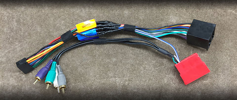
Your kit will come with a wiring harness that has been pinned and configured for your all three styles of factory stereo trim levels.
'98 - '02
If you purchased your kit with a radio the wire harness will already be soldered to the vehicle interface harness for you. Just plug it in. If you purchased the kit from us but have your own radio; you will need to make the connections from the vehicle interface harness to your radio harness.
These vehicles are true plug and play. Simply plug in the supplied harnesses and you are done.
The harness that we supply with your kit is setup to work with:
- Base Radio (no door speakers).
- Hi-Fi Sound System (door speakers but no separate subwoofer or Bose logo on door grills).
- Bose Sound System (Bose badge on door speaker grills, subwoofer behind rear seat in a coupe or in passenger's side foot well on cabriolet).
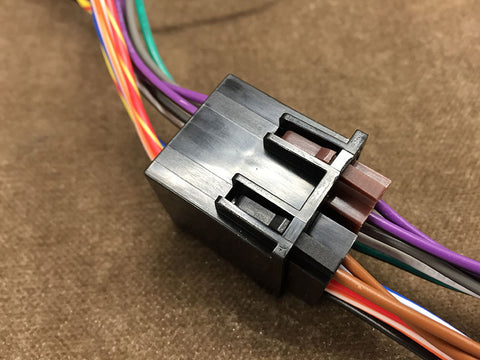
The large black female plug will mate with two different plugs from the vehicle. The first is the power plug. The second is the vehicle's speaker plug. Depending on the trim level of your car you may or may not have a populated speaker plug.
wire colors for the large black plug if you did not purchase a radio with your kit are:
- Yellow = 12 Volts Constant Power
- Red = 12 Volts Accessory Power
- Black = Ground
- Orange/White = Illumination
- Blue = Factory Antenna Amplifier turn-on
- Blue/White = Factory Amplifier turn-on
- White = Front Left Positive
- White/Black = Front Left Negative
- Grey = Front Right Positive
- Grey/Black = Front Right Negative
- Green = Rear Left Positve
- Green/Black = Rear Left Negative
- Violet = Rear Right Positive
- Violet/Black Rear Right Negative
Next connect the vehicles Yellow plug to the supplied Red plug. Note that the red plug is much larger than the yellow plug. The yellow plug should be located all the way to one side. Your vehicle may have other plugs that are along side the yellow plug (Blue and or Green). These plug are not needed but you can keep them in place if you like. These extra connections are for factory options such as a factory CD changer. Factory CD changers are not compatible with aftermarket radios. Some vehicles do not have a Yellow plug at all. If your vehicle does not have a yellow plug, do not be concerned. It is not needed for your application.

On the back side of the red plug you will see a Blue/White wire. This is the remote turn-on circuit for the factory amplifier. There are also 4 RCA connections. They are as follows:
- White = Left Front
- Grey = Right Front
- Green = Left Rear
- Violet = Right Rear
'03-'05 Vehicles
This generation of vehicles uses fiberoptic MOST bus for the factory radio accessory and illumination circuits. Harnesses for these kits come with two additional circuits added that must be connected.


- Red = Key-In Accessory
- Orange = Illumination
Red Key-In Accessory
This wire must be run directly to the ignition switch. Remove the heater duct under the driver's side of the dash. This duct section is easily removed, lie on the driver floor and slide the duct toward the left side of the car to disengage the inboard end-then slide it toward the middle of the car to disengage the outboard end where it connects to the short elbow leading to the left corner dash vent. This will allow better visibility and access. If you look at the back side of the ignition switch from under the dash you will find a double jacketed Orange wire. Tap into this Orange wire for accessory. This circuit will show 12 volts whenever the key is turned on and keeps power until the key is removed from the ignition cylinder.
This connection has been lengthened to reach from the radio location to the ignition switch. A 5 amp fuse and holder has been pre-installed for you.
Below: the back side of the ignition switch. Looking up from under the dash.

Orange Illumination
This wire must be run directly to an illumination source. This can be found at the cigarette lighter socket next to the radio. The cigarette lighter socket will have 3 wires running to it. The two thick wires are power. The thick brown wire is ground, and the third thin wire is illumination. This wire is typically grey with a blue stripe. Some vehicles are grey with a red stripe. Verify with a voltmeter to confirm. Connect the Orange wire from the radio harness to this circuit.
Video head unit safety:
Kenwood and Alpine video head units have connections to interface with the parking brake of your car (and the Alpine has an additional connection for the foot brake) which prevent viewing of videos while driving, and sometimes access to some menus. With Kenwood it’s a light green colored wire to connect to the parking brake’s single lead near the brake handle behind that adjacent side cover of the console. On the Alpine you also need to connect to the brake pedal wire, black/yellow or black/orange-on the plug on the brake pedal lever.
USB/iPod Cable Location in the Glove Box
The cable can be easily routed into the glove box by removing the glove box light. The light can be pried out (right side first). Notch the light opening enough for the cable to pass through with the light back in place.

Putting It All Together
Now you can plug in your radio's main harness, RCAs (if needed), antenna (using supplied antenna adapter), navigation antenna, and any other accessories that your radio may have. Slide the radio into the mounting cage. Once locked in place, the black trim ring that came with your kit can be snapped in place.

Other Relevant Installation Articles:
- 996 & 986 Amplifier Installation
- Satellite Antenna Mount Installation
- 996 & 986 Dash Speaker Installation
- Porsche Backup Camera Installation
- Retaining 996 Bose Factory Subwoofer