
996 Amplifier Installation
Installation summary:
Mount the new amplifier
In C4 996 models the new amplifier is mounted in the trunk where the factory CD changer would normally reside.
In C2 996 and 986 Boxster models the new amplifier is located in the same location, but vertical.
Wire the speakers to the new amplifier
The new amplifier kit will come with speaker output harnesses already connected to it. These speaker outputs will be loomed and marked. The factory amplifier will need to be disconnected and the factory amplifiers speaker outputs will need to be hardwired to the new amplifiers speaker output harness, wire by wire. There are 8 individual speaker connections total.
Route the cables into the battery compartment
Battery connections and signal cables will need to be routed through a large grommet and into the battery compartment.
Route remaining cables into the passenger compartment
The remaining cables (RCA signal, remote turn-on, optional rear speaker cable) will need to be routed through a second large grommet and into the passenger compartment.
Make connections at the radio
The last connections need to be made behind the radio.
Final adjustments
The amplifier has been preset for you before it was shipped to you. Some fine adjustments will need to be made after installation.

Installation Procedure
Your new amplifier will arrive fully assembled on the amp rack with all connections to the amplifier made for you. The first step will be to mount the amplifier assembly in place and decide which direction the cables will need to be routed.
Is your car a C4 or C2 body?
Tip: An easy way of determining if your car is a C4 or a C2 body is to look at how the spare tire is arranged in the trunk. A C2 has the spare located vertically in front of the battery compartment and a C4 has the spare located horizontally on the floor of the trunk under a carpeted cover.
Get the amplifier mounted C4
 The amplifier rack has several 3M Velcro strips already attached to the bottom mounting surface. A packet of 3M adhesion promoter is also secured to the bottom of the amplifier rack. Use the prep pad inside to apply the adhesion promoter to the carpeted surface of the amplifier location in the car. Allow to thoroughly dry before pressing the amp rack in place. The adhesion promoter will dramatically increase the holding power of the adhesive on the Velcro strips.

Remove the factory CD Changer. The amplifier will be mounted in the location of the factory CD changer. The factory amplifier is located under the plastic cover under the right side of the CD changer (Your left side as you look into the trunk). Remove the factory amplifier and unplug from the wire harness.
Amplifier Mounting C2
On C2 vehicles the amplifier is mounted vertically in the trunk as shown below. Under the amplifier there is a bolt hole pre-drilled into the amplifier mounting rack. Your kit comes with a single 2.5" long bolt that clamps the rack to the trunk wall. Place the amplifier rack in it's location without the amplifier on it, and drill a 1/4" hole through the trunk wall and into the battery compartment. Once the mounting hole has been drilled, remove the rack and proceed with routing your cables. The Last step will be to mount the amplifier and rack back in place after all cables have been routed into the battery compartment.
C2 Amplifier Location Pictured Below

C4 Amplifier Location Pictured Below

Mounting the Amplifier Rack - C2 Vehicles
The single bolt used to clamp the rack to the trunk wall is a 5/32" Allen type fastener with a 3/8" nut on the battery compartment side of the trunk wall.
Below: the location of the single rack mounting bolt is shown with the trunk liner removed from the vehicle for a better view. The bolt hole should end up between the populated grommet to the left of the yellow arrow and the empty grommet to the right of the yellow arrow. Be sure to look before drilling. The empty grommet is used to route all of your cabling into the battery compartment. The amplifier rack should be oriented so that the connection terminals are facing down. The trunk liner does not need to be removed when installing in a C2 vehicle.


Mounting the Amplifier Rack C4 Vehicles
On C4 vehicles the amplifier mounts horizontally in the factory CD changer location. Remove the CD changer and the two retaining clips that hold it in place. Amplifier racks for C4 vehicles come with a generous amount of 3M brand Velcro covering the bottom of the amplifier rack. The amplifier rack should be oriented so that the connection terminals of the amplifier are facing towards the passenger side or rear of the vehicle. Once the mounting location has been prepped, remove the entire trunk liner. The trunk liner is two separate parts. First remove the factory amplifier. The factory amplifier is in front of the spare tire on the drivers side. Before removing the second part of the trunk liner (part that is closest to the passenger compartment) remove the plastic dome cover. Unbolt the module that sits inside of the dome cover. Leave this module plugged in.

Re-Route the Factory Amplifier Harness
Once the trunk liner has been removed, identify the positive, negative, and data wires in the factory amplifier harness. These will be the only three wire that are not a twisted pair. 2002 and earlier non PCM vehicles will not have the data wire. Cut these circuits from the amplifier plug and insulate them. They will not be used. Warning: the Red/Blue 12V + is live.
Factory Amplifier Wires to Eliminate
Red/Blue = 12V +
Brown = 12V -
White/Red = Data
Cut the loops of cloth tape that hold the Orange fiber optic lines to the amplifier harness ('02 and up only). Separate the fiber optic lines and tie them up and out of the way. You will not be using these lines.

Cut the rest of the wires from the amplifier plug. These will all be speaker wires that are twisted pair. the brown stripe on each of these twisted pair indicates the negative polarity for that speaker. Pull the entire harness back towards the brake booster and re route as pictured so that the harness passes in front of the trunk wall. Tape or Velcro the harness in place, routing it to the left (your left) of the new amplifier location. The pocket between the new amplifier location and the passenger side fender is where you will make all of your connections to the new amplifiers speaker outputs.
Identify Speaker Connections at the Amplifier
 Your new amplifier will arrive with speaker output extensions already connected to it. These extensions are made with 4 conductor wire bundled in a white jacket. Each 4 conductor lead will have the following wire colors in it:
- Red = Right Positive
- Black = Right Negative
- White = Left Positive
- Green = Left Negative
Two of the 4 conductor cable will be marked with blue rings near the end of the wire loom. These rings are there to help identify which channels on the amplifier the cables are plugged into. They are as follows:
- No Ring = Channels A Left & A Right
- 1 Ring = Channels B Left & B Right
- 2 Rings = Sub Channel
(On the subwoofer output channel wire is standard 12 gauge speaker wire.)
Identify Speaker Connections at the Vehicle
Before identifying any speaker connections first identify the factory amplifier power and ground circuits. These will not be used in your installation. Identify them and tape them up so that they are separated from the rest of the wires.
Identify the speaker circuits in the factory amplifier wire harness. These will be in twisted pairs.

Above is an example of the factory amplifier plug that has been cut away from the amplifier and the wire colors that you will find in it. Colors may be different in your vehicle. Always test. The power and ground wires will be a larger gauge than the rest and will be at the far end of the plug. These wires are live. Insulate them and tape them off to the side so that they are not confused with speaker circuits. The speaker wires will all be twisted in pairs. Brown stripe indicates the negative side. Cut all of the circuits from the amplifier plug leaving about 2 inches of wire on the plug side just like the plug pictured above. This way the car can be returned to stock form in the future if needed. Make your connections to the new amplifier at the factory amplifier harness in the car. Not to the amplifier plug shown.
Speaker configuration
This amplifier can be configured in a couple of ways.
5 Channel Configuration #1
Dash tweeters and mid-range speakers are driven by channels 1 & 2.
Rear speakers are driven by channels 3 & 4.
Door woofers are driven by channel 5 (mono).
5 Channel Configuration #2
Dash tweeters and mid-range speakers are driven by channels 1 & 2.
Door woofers are driven by channels (3 &4 Stereo).
Aftermarket Subwoofer is driven by channel 5.
Rear speakers are driven by radio's internal amplifier.
5 channel configuration #2 is only used when an aftermarket subwoofer is being used in the system. Configuration can be used in conjunction with the factory Bose subwoofer (if equipped). For more information on retaining the factory Bose subwoofer please refer to this article link.
Testing Speaker Polarity & Location
To positively identify speaker position and electrical polarity (positive and negative terminals), use a 9 volt battery and temporarily touch the speaker wire pairs one set at a time. Do not hold the speaker wire to the battery for an extended amount of time. When the speaker leads are touched to the 9 volt battery the speaker will make a pop sound. On all Porsche models the brown stripe indicates negative polarity. The other wire will be positive. If you have any doubt, you can pull the speaker from its location and watch the direction of cone travel when touching the 9 volt battery to the speaker leads. The speaker cone will move outwards when the positive wire is touching the positive terminal on the 9 volt battery. If the speaker cone moves inward, the battery's positive terminal is touching the speakers negative lead. A second person comes in handy when testing. The second person can observe the speaker location for you. This whole test procedure will only take you a minute to conduct. If all of your speaker wire pairs have one wire with a brown stripe, then testing for polarity visually is not necessary.
Once you have identified each speaker circuit, make the appropriate connection to the supplied amplifier speaker output harness. These connections can be made with butt connectors. We prefer soldered connections.
Tip: make life easier on yourself when making soldered connections by stripping the wire back 1.5" so that you have a lot of surface area to twist together. This way you can twist several wire pairs at a time and they will hold their position without coming undone before you solder the connections.
Route the cables into the battery compartment
C4 Vehicles: Locate the large rubber grommet that separates the battery compartment from the trunk. On C4 vehicles this grommet has factory wires in it. notice that the factory wires are all grouped together and that there is plenty of room for additional cables to be passed through. Use a multi step drill bit or a paddle bit to drill an appropriate size hole for your cables. Then pull the grommet out from the car and slice the grommet from the outside edge into the hole that you drilled. Make sure that the grommet is only notched in the middle and not at the outer edge where the grommet meets the steel hole. You don't want your new cables to come into contact with the steel of the car. Run your cables through this grommet into the battery area (battery power, RCAs, Blue/Black Remote turn-on and reference ground). Wet the grommet with glass cleaner to make the grommet easier to push back into its hole.
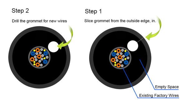
C2 Vehicles: On C2 vehicles there is a large grommet that is completely empty. Pull this grommet out from its hole in the steel. Once the grommet has been removed you can notch the grommet with a razor knife to make room for the cables. Make sure that the grommet is only notched in the middle and not at the outer edge where the grommet meets the steel hole. You don't want your new cables to come into contact with the steel of the car. Run your cables through this grommet into the battery area (battery power, RCAs, Blue/Black Remote turn-on and reference ground). Wet the grommet with glass cleaner to make the grommet easier to push back into its hole.
Ground the Amplifier
Ground your amplifier directly to the negative battery post. Cut the negative power cable to length and use the supplied ring terminal.
C4 cars can be grounded to the steel of the trunk floor if there is too little room in the battery compartment grommet. Grounding directly to the battery post is best but sometimes it is more reasonable to ground to the steel in the trunk. At the bottom of the trunk near where the trunk floor meets the side walls of the trunk there are areas that are double walled steel. These are ideal ground locations because you can use a power screwdriver to screw the ground ring terminal down without having the screw protrude through to the outside of the vehicle. This will keep the elements out and reduce the possibility of corrosion. Three grounding screws are included along with a lock washer. Use one screw and the lock washer through the center of the ground ring terminal. Then use a single screw on each side of the ring terminal to keep the ring terminal from being able to rotate loose.
Always sand all paint/primer off of the ground point so that there is good metal to metal contact between the body of the car and the ground ring terminal.
Crimping on the Ring Terminals
Use a set of professional wire crimpers like the ones pictured below. These type of crimpers can be found at your local home improvement store for around $25. The Klien Tools brand is a know good tool. Both power cables are intentionally left long. Trim to appropriate length.

Start by positioning the tooth of the crimpers on top of the seam in the ring terminal and make your first crimp.


Then turn the ring terminal on its side and crimp again. This will create a "B" crimp. This type of crimp is very strong.


Routing the cables through the battery compartment and into the passenger compartment.
Remove the 13 mm battery hold down bolt on the passenger side of the battery. Remove the negative battery terminal and slide the battery towards the passenger side of the vehicle. This will give you easy access to the large rubber grommet between the battery compartment and the passenger compartment. This grommet is located behind the drivers side of the battery. Inside of the vehicle this grommet is located just above the gas pedal. Signal (RCA), Remote (Black & Blue pair), and in some vehicles speaker wires will need to pass from the new amplifier location - through the first grommet - behind the battery - and through this grommet into the passenger compartment.
Mount the Fuse Holder
Now is a good time to mount the fuse holder and make your battery positive connection. Mount the fuse holder to the body support brace as pictured. Tip: You can also add two zip ties to the body of the fuse holder as well. To do this, remove the fuse holder cover and remove the fuse. You will see two slots in the bottom of the holder. Thread the zip ties through these slots and wrap around the body support brace.
Once your cables are routed into the passenger compartment, you will want to be aware of the vehicles main charge cable. This is a factory large gauge cable that runs the length of the vehicle. This cable connects the battery to the engine in the rear and is black in color. This cable emits a lot of electrical noise. You do not want your cables to run parallel to this cable. Never zip tie your cables to this cable. You must run your cables near and past this cable. Make sure that you cross it at a 90 degree angle. this will dramatically reduce any electrical noise transfer. Below is an image of the factory charge cable.

When routing cables be aware of the gas and brake pedal operation. Keep clear of them.
Once your cables are in the vehicle and the grommet is put back in place, reconnect the battery's negative terminal, and refasten the battery hold down.
Make Connections at Radio
Connect the Blue and Black wire harness to the radio. Blue is amplifier remote turn-on and is connected to the Blue with white stripe wire on the aftermarket radio. If you purchased a radio with your amplifier, these connections will have a matching plug. Simply plug it in. The Black wire that is run inside of the same loom as the Blue wire is the amplifier reference ground. Use this wire to ground your radio. Do not use the radio ground in the factory radio wire harness. The goal is to make sure that both the amplifier and the radio share the exact same potential to ground. This will greatly reduce any chance of electrical noise entering the audio system.
Connect the rear speaker pass through. Only for amplifier configurations where the rear speakers are being driven from the radio and not the new amplifier. In the event that the rear speakers need to be driven by the radios internal amplifier, we include a speaker wire run that connects to the radio harness and runs into the trunk where it connects to the factory amplifier harness with the other speaker connections. If you purchased a radio with your kit, the radio will already have a mating connector on it for this cable. Simply plug it in.
Route all 3 pairs of RCA cables from radio cavity to the front trunk, label them first to identify front/rear/sub.
Final Adjustments
Even tough settings on your amplifier have been pre-set for you there are still some fine tune adjustments to make.
Check all of your crossover settings.
Basic crossover settings have been pre-set for you before your amplifier leaves our facility. Some adjustment will still be required.
The crossover setting sets the lowest or highest frequency that your amplifier will send to a particular speaker. HP indicates high pass and will not allow low frequency sounds to be passed to a speaker. The cut off frequency is determined by the corresponding dial. HP mode should be used on both your dash speakers as well as the rear speakers. A typical frequency setting for these types of speakers is 200 - 300 Hz. Exact frequency selection depends on the speaker being used (factory or aftermarket). Higher frequency selection will be less demanding on the speaker.
LP indicates low pass and would not allow high frequency sounds to be passed to the woofers of the audio system. This type of crossover would be used for door woofers and subwoofers. Typical frequency ranges for these type of speakers is 80 - 300 Hz. Exact frequency selection depends on the speaker being used (factory or aftermarket). Higher frequency selection is normally used with factory speakers and lower frequency selection is normally used with aftermarket subwoofers. A good starting point is to have your LP crossovers set to the same frequency as the HP point of your other speakers.
Check your gain levels.
Each pair of audio channels have a gain adjustment (level). This is used to adjust all of the speakers outputs to a normalized level. If the rear speakers are too loud in comparison to the front speakers, then turn the level of the rear speaker channels down. The same goes for all other channels. For example if the subwoofer is overbearing then turn the subwoofer level down.
Final level
At the end of the day you want the gain levels of all channels to be as low as possible yet be high enough that your new audio system can reach the volume levels that you desire. If the gain levels are too high, electrical noises will be picked up by the amplifier. This can be heard through the speakers as a high pitched whine as the engine is revved. Also gain levels that are too high will cause an audible hiss to develop at low radio volume levels.
You should be able to achieve silence in the audio system with the radio volume at or near zero, yet still be able to turn up the volume and get high levels of quality sound.